Elite Hotel event

Elite Hotel Exhibition 2024 Tehran

Elite Hotel event

2024 June 27

Read time : 8 m

Share:

Elite Hotel Exhibition 2024 Tehran

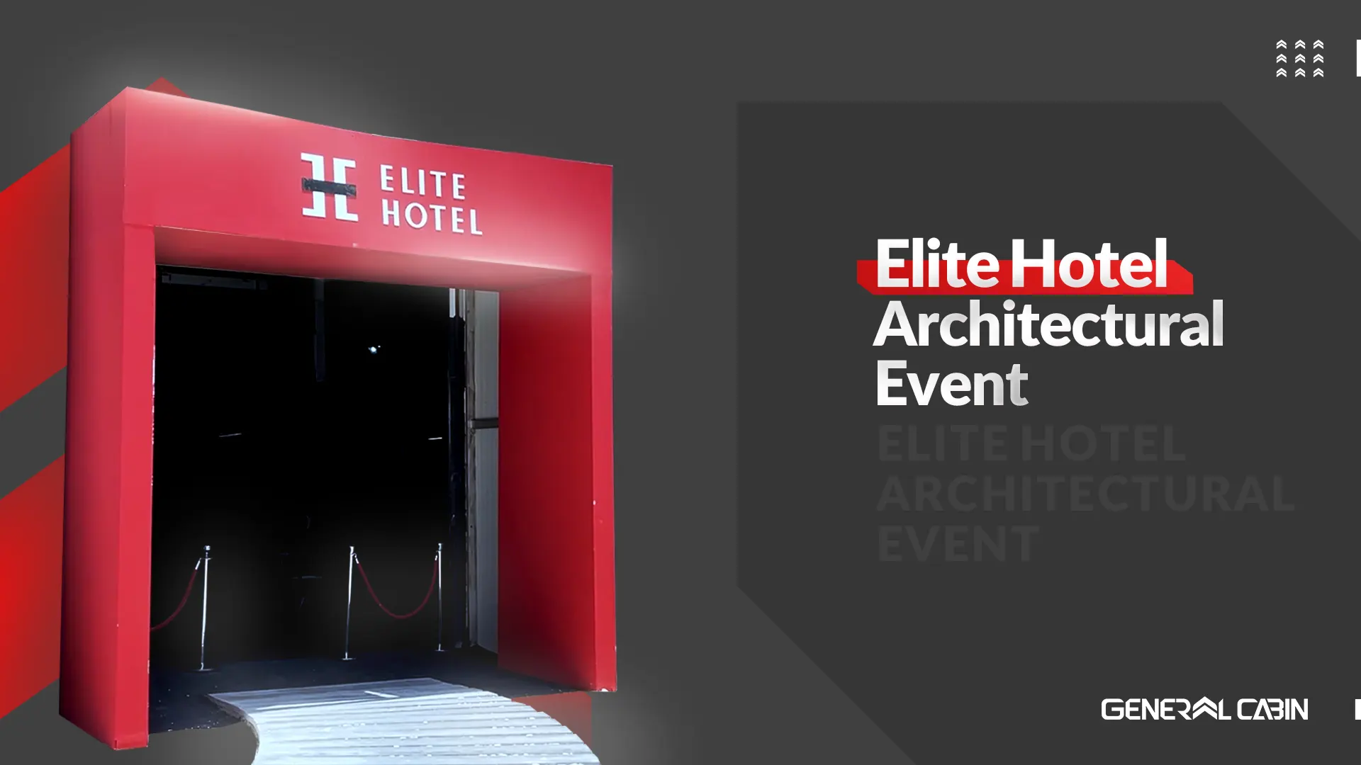
The Elite Hotel Exhibition 2024 Tehran, one of the prominent specialized events, was held for 6 days at the Milad Tower Exhibition Center. This event aimed to introduce top products in the building and hospitality industry, providing a platform for brand owners, professionals, and the general public to closely familiarize themselves with the quantitative and qualitative aspects of Iranian and foreign products.

In today’s world, holding specialized events to create effective and direct connections is one of the best product presentation methods. These exhibitions, in addition to offering the opportunity to experience products firsthand, facilitate interaction and information exchange between exhibitors and visitors. However, the challenges in presentation methods and the limitations of exhibition spaces usually reduce the quality of interactions.

The Elite Hotel Exhibition, designed to overcome these challenges and offer a different experience, allowed visitors to get acquainted with various products and brands in a simulated and realistic environment. This space enabled detailed observation and interaction with the products, creating a memorable visual and experiential impression of product quality in the minds of visitors.

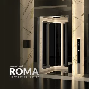
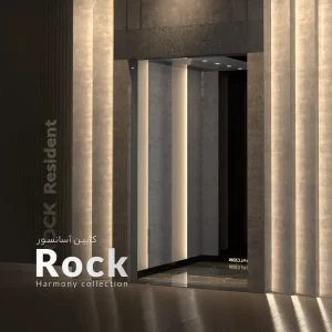
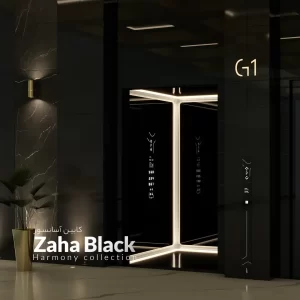
At this event, 52 leading companies in the building industry showcased their products through catalogs and store samples. One of the companies that had a successful presence was General Cabin, which displayed the Zaha Black, Monaco, and Dayton cabins. These products were well-received, demonstrating domestic production’s high capability and quality.

The organizers of this exhibition, aiming to create a sense of demand and guide customers towards the showcased resources and brands, provided a fully simulated environment using a package of products. This approach resulted in targeted connections between buyers and sellers and created a unique and memorable experience for visitors.

The Elite Hotel Exhibition 2024 Tehran concluded successfully, demonstrating that the use of new formats and innovative spaces can significantly enhance and improve the level of interactions and attract customers. It is hoped that such events will continue to be held in the future, providing an appropriate platform for introducing and presenting top products.

What do you think about this article?

Share your opinion with us

فلکه هرزگرد

Elevator Sheave

فلکه هرزگرد

2024 June 24

Read time : 14 m

Share:

Types of Sheaves

Elevator sheaves are categorized into two types: deflecting and reversing. Depending on the type of elevator, different sheaves are used. In some elevators, a reversing sheave optimizes the alpha angle. In other elevators, sheaves are used to change the direction of the hoisting ropes and guide them. The grooves in these types of sheaves do not create traction and only serve to guide the hoisting ropes.

General Specifications of Elevator Sheaves

The diameter ratio of the sheave should be at least 40 times the nominal diameter of the hoisting rope.

Cast iron is used in the manufacturing of elevator sheaves, offering the following advantages:

  • Good castability
  • High compressive strength
  • Use of dampers to reduce vibrations
  • Excellent sliding properties
  • Ability to stop or rotate in an emergency
  • High resistance to corrosion

The hardness of the cast sheave depends on its chemical composition, and the acceptable hardness for the traction sheave is between 160 and 200 Brinell.

فلکه هرزگرد

Polyamide Sheave

Due to the heavy weight of cast iron materials and the challenges encountered during the casting, machining, finishing, and painting processes in the production of elevator sheaves, the entire process of manufacturing cast iron sheaves is fraught with complexities and numerous challenges. Those knowledgeable in this field understand the characteristics and issues associated with producing cast iron sheaves from start to finish.

The issues and problems with cast iron sheaves are as follows:

  • Need for a furnace with an appropriate temperature
  • Transporting raw materials to the casting site
  • Mixing and melting various materials
  • Preparing the mold
  • Mold setting with casting sand
  • Injecting molten materials
  • Cooling the cast materials and removing the sheave
  • Turning and machining
  • Wear and tear on various turning tools
  • Preparing the shaft and bearing seats
  • Separating defective sheaves with voids and cracks
  • Painting

Given the extensive workload and high costs involved in the production stages of cast iron sheaves, industrialists and manufacturers of sheaves or elevator pulleys have considered alternative materials. Some major companies have replaced casting materials with PVC nylon, polyurethane, and high-density polyethylene (HDPE) to produce elevator sheaves. Many manufacturers have recently started producing and replacing plastic sheaves instead of cast iron sheaves.

فلکه هرزگرد

MC Nylon

MC Nylon is one of the plastic materials that has widely replaced steel and cast iron in the industrial world, especially in the elevator and escalator industry, and it offers the following advantages:

  • Lower cost and greater savings compared to cast iron sheaves
  • High hardness and resistance to friction
  • Long lifespan against corrosion
  • Lightweight and easy to transport, making installation easier for technicians
  • Reduced noise, low vibration, and oscillation
  • Smooth movement of hoisting ropes over it, providing a quiet and smooth ride for elevator passengers
  • Prevents hoisting rope wear and increases its durability and lifespan
  • High resistance to moisture and direct sunlight
  • No need for oiling or greasing
  • Available in white and yellow colors
  • No wear and production of fine dust, environmentally friendly


One of the crucial elevator components is the idler or traction sheave. This sheave refers to the pulley used for transmitting motor power and moving the hoisting ropes in the elevator.

The timing of idler sheave replacement depends on the wear level of the elevator sheave. If the bearing of the sheave encounters a problem, it is possible to replace the bearing; however, in such cases, the best course of action is to replace the elevator idler sheave. Signs that indicate the need for replacement include:

  • Presence of iron filings around the motor sheave and elevator idler sheave
  • Formation of spiral grooves in the sheave grooves, indicating the passage of the hoisting rope over the grooves
  • Indentations of the hoisting rope inside the grooves
فلکه هرزگرد

Factors Influencing the Installation of the Deflector Sheave

  • Design and Use: The deflector sheave must be designed and utilized according to the nominal speed and load of the elevator.
  • High Resistance: The deflector sheave must be resistant to bending and torsional stresses.
  • Precise Angle: The angle between the deflector sheave and the gearbox sheave must be precise and calculated.
  • Bearing Balance: The bearing of the deflector sheave must be balanced without any play.
  • Sheave Health: The deflector sheave must be healthy and free from any cracks or roughness.
  • Appropriate Grooves: The grooves of the deflector sheave must be larger than the diameter of the wire rope.

Corrosion and Damage of the Sheave

The reasons for the corrosion and damage of the deflector sheave are as follows:

  • Imbalance of the Counterweight and Cabin: An imbalance between the counterweight and the elevator cabin is one of the main reasons for sheave corrosion. To prevent this issue, installers must carefully balance the counterweight and cabin.
  • Dry Wire Rope: A dry elevator wire rope can lead to sheave corrosion. The service technician must check the wire rope monthly and lubricate it if necessary.
  • Misalignment of the Motor Sheave and Deflector Sheave: The motor sheave and deflector sheave must be aligned and in line with the elevator cabin. Otherwise, the deflector sheave will suffer from corrosion over time. To prevent this issue, installers must ensure the alignment of these two components during the elevator installation.
فلکه هرزگرد

Alpha Angle

The alpha angle of the wire rope is one of the critical angles in elevator installation calculations that must be calculated precisely. Wire ropes play an important role in the traction of the elevator; the motor pulley must perform the dual functions of moving and shifting the elevator and changing the direction of the force.

The alpha angle, or Angel of warp, is formed between the main motor sheave and the deflector sheave and must be selected in such a way that, during the rotation of the wire rope on the sheaves, it is in the best condition in terms of safety, speed, balance, and power. The cabin and counterweights are suspended on either side of the motor sheave, and this system is designed and executed through wire ropes by the sheaves.

If an appropriate alpha angle is not considered during the installation of the elevator deflector sheave and gearbox sheaves, it will cause the elevator to slip.

Formula for Calculating the Alpha Angle in Elevators

The calculation of the reverse bend in the suspension system plays an important role and must be considered during the elevator design. There are two methods, approximate and precise, to determine this angle, which are discussed below.

Approximate Method for Calculating the Alpha Angle:

An approximate method used to determine the alpha angle in an elevator has an error range of 10 to 15 degrees. The minimum alpha angle for an elevator should be 150 degrees, and the maximum should be 180 degrees.

To calculate the alpha angle, follow these steps:

  1. Measure the length of the wire rope on the gearbox motor sheave.
  2. Multiply the obtained value by 360.
  3. Divide the calculated value by the circumference of the gearbox sheave.

(3.14 * sheave diameter) / (360 * length of the wire rope lying on the motor sheave) = alpha angle

α = (L * 360 / πd)


Accurate Method for Determining the Alpha Angle

To determine the alpha angle using this method, the sine of the complementary angle is used; therefore, the alpha angle can be measured with high accuracy. The parameters Rs, Rp, I, and h respectively represent the radius of the traction sheave, the radius of the deflector sheave, the horizontal distance between the centers of the two sheaves, and the vertical distance between the centers of the traction and deflector sheaves.

What do you think about this article?

Share your opinion with us

Elevator rail

Elevator Rails

Elevator rail

2024 June 18

Read time : 11 m

Share:

Elevator Rails

Elevator rails are essential and practical components in elevator systems, responsible for guiding the cabin and balancing the weight frame during vertical movement. These rails also restrict horizontal movements of the cabin across different floors. All elevator rails are manufactured from high-quality, premium steel and must be produced without bends, or twists, and with a smooth surface to ensure optimal performance and system safety.

Elevator rails are produced in various thicknesses, with a T-shaped cross-section, and in 5-meter branches. These rails can stop the cabin during the operation of safety mechanisms and prevent oscillations caused by forces displacing passengers away from the center.

To connect the rails, a component called a fishplate is used, while brackets and plates secure the rails to the elevator shaft structure. It’s important to note that the balance weight bracket differs from the rail bracket; therefore, a corner bracket is used for the balance weight and an OTC bracket for the rails. Appropriate brackets are selected depending on the size and type of rails, each accompanied by two plates to hold the rail securely.

These details and considerations in the production and installation of elevator rails play a crucial role in enhancing the safety and efficiency of elevator systems.

Elevator Rail Features

To install elevator rails, suitable rails with the following features must be selected:

  • The rails should be made of high-quality ST-37 structural steel.
  • The rail surface must be completely smooth, uniform, and without any curvature.

Note: According to the specifications of the purchased rail catalog, the tensile stress number of the rail should be between 370 and 520 Newtons per square millimeter.

Safety considerations in elevator rail installation calculations:

  • The surface of the rails should be free of twists and bends.
  • Guide rails and their parts and connections must have high resistance to applied forces.
  • Rails must be installed in the elevator shaft parallel and perfectly plumb.
  • During rail installation, the tongue and groove at both ends of the rail must fit together well.
Elevator rail ریل آسانسور

Functions of Elevator Rails

Elevator rails are designed in a T-shape and play an important role in the vertical movement of the elevator cabin. Generally, the primary functions of elevator rails are to guide the movement of the cabin and the counterweight along a specified path, reduce lateral movements of the cabin, and ensure its safe movement.

Reviewing the complete specifications of various elevator rail dimensions:

To accurately procure elevator rails, their technical specifications must be reviewed according to the table of different rail dimensions and the methods of producing hot-rolled and cold-rolled rails.

Elevator Rail

Elevator Rail Bracket

Elevator rail brackets are essentially used as mounting bases for the rails. By using these brackets and fishplates, the elevator rail is installed onto the wall or shaft structure. Various factors such as cabin capacity, rail dimensions, parachute, and elevator speed determine the type and size of the bracket.

Elevator rail brackets serve multiple purposes, including securing the counterweight and cabin rails, connecting the guide rails to the metal structure of the shaft, attaching the rails to the concrete wall of the shaft, and ensuring the proper alignment of the elevator shaft wall.

The location for installing the elevator rail bracket determines the position for installing the elevator rail after the brackets are mounted. Therefore, the brackets must be installed in the correct and precise positions.

Elevator rail ریل آسانسور

Elevator Clamp

The elevator clamp varies depending on the type of elevator and the length of the rail, and it must remain firmly and securely in place over the years of elevator use. There are various sizes of clamps available for different rails.

Conditions for installing the elevator rail clamp include:

  1. Place the entire surface of the clamp on the rail bracket.
  2. Welding on the sides of the clamp near the surface of the bracket is prohibited.

For installing the elevator clamp and bracket, the bracket and clamp must be ordered based on the type of elevator rail and the method of securing it. First, the elevator bracket, including the weight bracket and cabin bracket, should be installed. Then, place the clamp against the bracket’s bolt holes and insert the specified bolt. Next, for distance adjustment, insert the required shim, flat washer, spring washer, and nut onto the bolt and tighten it securely.

Elevator rail ریل آسانسور

What do you think about this article?

Share your opinion with us

کارسلینگ آسانسورهای هیدرولیک

Car sling: Key Component in Elevators

کارسلینگ آسانسورهای هیدرولیک

2024 June 12

Read time : 12 m

Share:

Car sling: Key Component in Elevators

car sling is a fundamental tool predominantly used in hydraulic elevators and rarely in traction elevators. In hydraulic elevators with Side Direct and Indirect systems, the car sling serves as the cabin’s frame. Shoes, rollers, and the parachute are mounted on the car sling, which means the cabin lacks a yoke.

In Indirect systems, a sheave (pulley), shoes, and a frame are assembled on the jack and connected to the car sling via wire ropes. In contrast, in Direct elevators, the car sling lacks a pulley and a parachute. In hydraulic elevators that use car sling, only one pair of rails is required, and these rails are responsible for guiding the jack, the pulley attached to it, and the car sling.

car sling is mostly used in hydraulic elevators but can also be found in traction elevators. The elevator cabin is placed on the car sling, and in addition to the cabin, the emergency braking system or parachute is also installed on the car sling. The elevator jacks exert their driving force on the car sling, causing the cabin to move.

In hydraulic elevators using the car sling system, only one pair of rails is needed for operation. These rails can simultaneously guide the car sling, the jack connected to it, and the idler pulley connected to the jack. In hydraulic elevators, car sling installation is done using two pairs of guide rails, while in traction elevators, a car sling is installed in a reverse and parallel rail setup.

کارسلینگ آسانسورهای هیدرولیک

Benefits of Using Car Sling

Using a car sling in hydraulic elevators has numerous advantages. Firstly, it offers easier installation and setup compared to other systems. Secondly, it requires less space in the elevator shaft, as only a pair of rails is sufficient for guidance. Thirdly, due to its simple design and being less costly than more complex systems, the car sling is widely used in various construction projects.

The car sling is a key component in the design and construction of hydraulic and traction elevators, contributing to increased safety and efficiency with its simple installation and high performance. Given its technical features and practical benefits, the car sling is recognized as an effective solution in the elevator industry.

کارسلینگ آسانسورهای هیدرولیک

Types of Elevator Car Slings

In hydraulic elevators, car slings are classified into two main categories based on the type of jack: direct side jacks and indirect side jacks.

Direct Side Hydraulic Elevator Car Sling:

The direct side jack car sling has a simple structure and lacks certain components such as a safety gear (parachute), sheave, rope clamp, and other accessories. However, this type of car sling includes a structure that must be strong enough to transfer the jack’s force effectively. The adjustability (regulation) of this car sling depends on the length of the part that needs to be connected to the jack, and the adjustment is usually higher than the leveling of the top shoes of the car sling.

کارسلینگ آسانسورهای هیدرولیک

Indirect Side Hydraulic Elevator Car Sling:

The indirect side jack car sling, also known as a 1:2 car sling, is used in indirect systems. The connection of these jacks to the cabin or car sling is done through a sheave and wire rope. Due to the use of wire rope, this car sling must be equipped with safety gear, which is chosen to be an instantaneous type that can operate without a governor. In an indirect side hydraulic elevator car sling, the jack is placed on a base, and its size varies depending on the height of the shaft, the pit, the stroke of the jack, and the length of the jack.

Components of Indirect Side Car Sling:

The indirect side car sling consists of smaller parts such as a jack connection bracket, jack holder, deflection sheave, safety gear, flat and roller shoes, rope clamp, hydraulic sheave, and the car sling structure, including columns, forks, and the jack base column. These components combine to provide a solid and stable structure that can effectively withstand various forces.

Hydraulic elevator car slings comprise numerous primary and secondary components that offer precise design and high performance. One of the main advantages of using car slings in hydraulic elevators is the possibility of using only a pair of rails to guide the car sling, jack, and deflection sheave simultaneously, which reduces costs and simplifies installation and setup.

Elevator Car Sling Structure

The structure or framework is considered the main component in a hydraulic elevator car sling. It must be capable of bearing the weight of the cabin, its load, and the torques exerted by them. This structure is designed in an L-shape, comprising two vertical columns and two horizontal beams known as car sling forks. In this configuration, the cabin rests on the forks and is connected to the columns from the ceiling. Shoes, rollers, and parachutes are also securely attached to the car sling columns.

To enhance the efficiency and proper functioning of the car sling columns and forks across various shaft and cabin dimensions, their lengths should be adjustable. High-quality versions of this component are constructed with bolts and nuts, allowing them to be easily assembled and disassembled.

کارسلینگ آسانسورهای هیدرولیک

Hydraulic Elevator Car Sling Guide Shoe:

Shoes are used between the car sling and the rail, available in various types. Typically, two types of shoes are used in the car sling: roller shoes and flat shoes. Due to the greater force exerted by hydraulic car slings on the guide rails, the shoes must have high mechanical resistance. Roller shoes offer higher resistance to the torques exerted and are often used at the bottom of the car sling.


Car Sling Parachute:

The parachute in the car sling is used to prevent the cabin from falling in the event of a sudden breakage of the wire ropes. In all hydraulic elevators with indirect jack car slings and wire ropes, the installation of an instantaneous parachute is deemed essential. In car slings without a governor, the parachute is triggered by a mechanical system comprising plates, springs, and links.

Due to its robust and efficient design, the hydraulic elevator car sling structure plays a critical role in the safety and performance of the elevator. With the ability to adjust the length of the columns and forks, this structure can easily adapt to various shaft and cabin dimensions. This feature facilitates the easy installation and adjustment of the car sling at the project site.

When selecting a car sling, special attention should be paid to the quality of its construction and the materials used. Bolt-and-nut car slings, due to their ease of assembly and disassembly, are considered suitable options for various projects. Additionally, high-quality shoes and reliable parachutes should be used to ensure the safety and proper functioning of the system.

کارسلینگ آسانسورهای هیدرولیک

What do you think about this article?

Share your opinion with us

Jack in Hydraulic elevators

The structure of Jack in Hydraulic elevators

Jack in Hydraulic elevators

2024 June 9

Read time : 10 m

Share:

Overall Structure of a Simple Jack

Cylinder: The cylinder is a cylindrical component forming the external part of the jack. Its inner surface must be very smooth and polished, and it needs to be highly resistant to the pressures applied and corrosion due to environmental moisture.

Piston: The piston is a cylindrical part inside the cylinder, with its end connected to the cabin. It moves under oil pressure, causing the cabin to move. The piston must be highly precise, polished, and sufficiently resistant to static and dynamic load pressures.

Rupture Valve: The rupture valve is the most sensitive and important part of a jack, assembled on the jack cylinder and as the connection between the hydraulic hose and the jack. Oil enters or exits the jack through this valve. Whether the jack is buried underground or installed above ground, the safety valve is mounted at the bottom or top of the jack. It controls the volume of oil passing through, and if the cabin speed exceeds the limit or the hydraulic hose breaks, it stops the oil flow, causing the cabin to stop. The safety valve activation ensures a gradual and shock-free stop of the elevator. The safety valve is tested and adjusted at the factory, but the installer makes the final adjustment based on the nominal speed plus 0.3 meters per second.

جک آسانسور هیدرولیک

Types of Elevator Jacks Based on Structural Differences

Jacks are produced in single-stage and multi-stage types. Single-stage jacks have a simpler structure and are always cheaper than telescopic jacks. The maximum allowable static pressure for single-stage jacks is 45 bar, and for telescopic jacks, it is 40 bar. Telescopic jacks require less space beneath the cabin, making them logical to use in cases with limited pit space. Telescopic jacks are usually produced in two-stage (Stage 2) and three-stage (Stage 3) types. In some projects with long travel distances, due to transportation and installation constraints in the elevator shaft, single-stage jacks are produced in two pieces (2 Pieces) and assembled on-site.

جک آسانسور هیدرولیک

Diversity in Jack Installation and Force Transmission to the Cabin

Force transmission to the cabin can be done in two ways: direct and indirect.

Direct: In the direct method, the piston is directly connected to the cabin, and the speed and movement of the jack are always equal to the cabin’s movement. This is the simplest and safest jack installation method, commonly used in freight elevators with high capacity and low-rise buildings. The limitation of this method is in buildings with long travel distances, a jack as long as the travel distance must be made and installed in the elevator shaft. This limitation leads to the use of the indirect method.

Direct connection of the jack to the cabin can be done in two ways:

– Central Direct Jack: The jack is directly connected to the bottom of the cabin, maximizing the use of the elevator shaft space for the cabin. However, the hydraulic jack needs to be buried in the ground.

– Side Direct Jack: The jack is directly connected to the bottom of the cabin’s yoke, which is referred to as side direct. This method uses some of the elevator pit space for the jack, leaving less room for the cabin, but requires less digging and burying of the jack.

جک آسانسور هیدرولیک

Indirect: In this method, the piston moves a pulley, which, through several wire ropes (one end attached to the cabin and the other to the pit floor anchored under the jack), moves the cabin. The cabin’s speed and movement are doubled, making this method known as the 1:2 system. Indirect jack installation allows the use of a jack with half the travel length, leading to economic savings in many projects. To maintain safety standards, besides the rupture valve, a parachute system must be used. In the indirect method, the jack is always placed beside or behind the cabin. In some high-capacity projects with large cabins, both direct and indirect systems use two jacks to connect and move the cabins, referred to as the double method.

What do you think about this article?

Share your opinion with us

آسانسور گیرلس

Gearless Elevators

آسانسور گیرلس

2024 June 2

Read time : 13m

Share:

Gearless Elevators

Gearless Elevators are systems where the motor operates without using a gearbox. In these systems, an inverter or speed control drive is utilized to regulate the speed of the traction sheave. This type of elevator motor is of the permanent magnet variety, offering higher efficiency than geared motors. Older gearless elevators used DC motors that allowed precise control of positive and negative acceleration curves. However, modern technology employs AC motors, leveraging permanent magnet construction and electronic advances.

Gearless Elevators (gearless traction elevators) are a type of electric elevator where the motor is directly connected to the pulley without using mechanical gears to transfer power. These elevators are particularly popular in tall buildings and large residential and commercial towers due to their numerous advantages.


Types of Gearless Motors

  • Permanent Magnet AC Motor
  • Variable Voltage and Frequency AC Motor
  • Variable Voltage DC Motor

Differences Between Gearless and Geared Elevator Motors

The most noticeable difference between gearless and geared elevators is the reduced vibration and shaking in gearless elevators due to the absence of a gearbox. Gearless motors do not require lubrication, whereas the lack of timely lubrication can damage geared motors.

Regarding motor speed, gearless elevators operate at around 150 RPM, generating less noise compared to geared motors operating at around 1500 RPM. Additionally, geared motors in busy buildings heat up more quickly, causing temperature sensors to shut the motor off automatically for cooling. Gearless motors typically do not have this overheating issue.

Geared motors require two to three times more force to start compared to gearless motors. Efficiency-wise, gearless motors boast a 98% efficiency rate, significantly higher than the 50% efficiency of geared motors, meaning geared motors consume twice as much energy.

Gearless motors are also smaller and lighter than geared motors, making them easier to install in machine room-less (MRL) elevators.

آسانسور گیرلس

Advantages of Gearless Elevator Motors

  • Easy installation
  • Requires less space due to smaller size
  • 98% efficiency rate
  • No need for constant lubrication
  • Performs well during peak traffic hours
  • No need for a cooling system
  • Can be installed without a machine room
  • Durable components with a long lifespan
  • Quiet operation
  • High-quality elevator movement

Disadvantages of Gearless Elevator Motors

  • High initial cost (although cost-effective in the long run)
  • Requires precision in selecting components
  • Poor performance in industrial environments with harmful particles
  • Requires a position sensor (encoder)
  • Strong brakes are needed for independent stopping in emergencies due to the lack of a gearbox
  • Installation and setup must be done by specialists
  • Lack of sufficient experience and information among elevator companies and service technicians
  •  
آسانسور گیرلس

Components of a Gearless Elevator Motor

  • Each gearless elevator motor consists of the following components:

    • Drive motor
    • Traction sheave
    • Frame
    • Direct current rotor or armature
    • Protective bearings
    • Magnetic brake


    Some parts, such as gears, worms, high-speed bearings, flywheels, and couplings, are not present in gearless motors. These motors also do not require oil or lubrication.

Development and Features of Gearless Elevator Motors

  • In the 1980s, the gearless elevator motor emerged as a result of advancements addressing the shortcomings of earlier elevator motor models. Gearless motors, also known as AC motors, control the output voltage and frequency to ensure smooth elevator movement.

    The development of gearless motors has progressed to the extent that, although only a few companies produced compatible equipment a few years ago, now many companies worldwide can design and manufacture equipment compatible with gearless elevator motors. Due to the exceptional advantages of gearless motors, there is an increasing trend among elevator companies to adopt this technology.

    While the internal mechanism of gearless motors is better suited for high-speed elevators (usually around 2.5 meters per second), they are also commonly used in lower-speed elevators.

آسانسور گیرلس

Features of AC Motors

  • AC motors offer more advanced technology compared to other types, resulting in higher mechanical efficiency than geared traction motors. Additionally, the electrical efficiency of AC motors surpasses that of induction traction motors (DC). Permanent magnet motors are smaller in size and require less space, eliminating the need for a large machine room and allowing for machine room-less (MRL) installation.

    Another significant advantage of these motors is that their maintenance costs are relatively low, requiring less frequent and extensive maintenance. Their specific construction also results in fewer breakdowns, thus reducing repair costs.

آسانسور گیرلس

A History of the Emergence and Functional Objectives of Gearless Motors

Electromechanical motors are produced in two types: DC and AC. DC motors are suitable for applications requiring smooth, quiet, and precise movement. These motors are controlled using a DC generator with variable output. In the 1980s, drives replaced DC generators due to innovations. Here are some advantages of using drives:

  • Higher efficiency of drives compared to DC generators
  • Better control of drives
  • Improved motion quality using drives
  • Frequency control
  • Voltage control


The emergence of drive technology in the elevator industry led to the development of gearless AC motors, which made the movement and stopping of elevators more precise and comfortable. Older elevators with gearless motors, known as Ward Leonard elevators, used DC motors. However, with the advancement of drive technology, the motion quality of DC gearless motors improved, and higher speeds became achievable. Consequently, the following types of gearless motors were introduced:

  1. Drum or Barrel Gearless Motor: In this type, the rotor of the elevator motor is located internally.

It is recommended to install drum or barrel gearless motors in machine room-less (MRL) elevators for the following reasons:

  • Small dimensions
  • Possibility of installation in the elevator shaft
  1. Disc or Flat Gearless Motor: In this type of gearless motor, the rotor is located externally.

The disc or flat gearless motor also has many advantages, the most important of which are the very small dimensions of the motor, smooth cabin movement, and the very high speed of the elevator.

آسانسور گیرلس Gearless elevator

Elevator Design with Gearless Motors

A drive system is typically used to operate a gearless motor. The drive is responsible for converting three-phase AC power to DC. Next, the required voltages and frequencies are injected into the elevator’s gearless motor as AC power by the drive. Since the drive is responsible for converting DC power to AC, it is also called an inverter.

The elevator’s gearless motor generates electricity in the following two scenarios:

  • Moving downwards with more than half capacity
  • Moving upwards with less than half capacity

This electricity is generated unintentionally and must be used; otherwise, it can cause serious damage to the inverter. Therefore, in elevators with gearless motors, a system called a brake resistor is installed to prevent damage to the inverter. The brake resistor converts the generated electricity into heat. Given the high rate of this current in very tall buildings, it is possible to return this current to the building’s power grid.

Safety System of Gearless Motors

In gearless elevators, the brake is an external collapsible type equipped with two shoes. The brake system in the elevator motor is also designed to open internally. Generally, the brake in the gearless elevator system is designed to operate independently and stop the cabin before the parachute is activated.

When evaluating the quality of the shoes used in the gearless elevator brake system, the following points should be considered:

  • Resistance to scratching and abrasion
  • Desirable wear characteristics
  • Acceptable elasticity
  • High thermal and motion resistance
  • Strength against moisture and other damaging natural factors
آسانسور گیرلس Gearless elevator

What do you think about this article?

Share your opinion with us